
Today we are releasing version 6.0 of the Tactile Universe Blender add-on. This update brings with it several major improvements to the add-on:
- All add-on parameters are directly associated with the Blender objects meaning that they can be adjusted at any time. This includes after the object has been deselected or even after the
.blendfile has been saved and re-opened. - Internally, the code has been optimized to make it faster.
- All add-ons work in “object mode”, no need to enter “edit mode” anymore.
- The holder and name plate both have an additional modifier applied to make them single objects rather than a collection of separated parts. This makes them easier to select in Blender and the exported STL files easier to work with inside slicers.
- All command line scripts have been updated to work with the new plugin.
The latest version of the add-on can be found on GitHub releases page.
This update changes the workflow for creating Tactile Universe models in blender, the following tutorial will walk through these changes.
Setting up Blender
This process has not changed since the last update, see the “setting up Blender” section of Tactile Universe add-on v5.0 for step-by-step instructions.
Making your own models
This is a recap of 2. How to make your own models using the latest version of the TU add-on.
1. Import an image
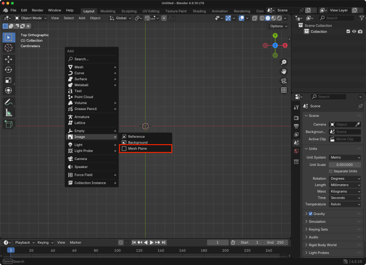
To import an image press shift + a to bring up the add object menu, go to Image > Mesh Plane.
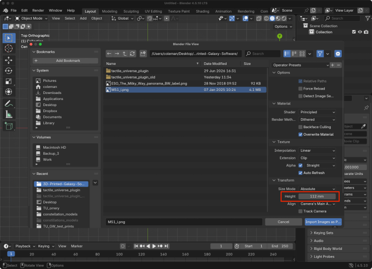
In the file selection box, navigate to the image you want to make a model for. On the right-hand side of the window, make sure to set the height of the model in millimeters. We typically use a height of 112 mm. The add-on includes an image of M51 you can use for testing.
2. Use the Emboss Plane add-on
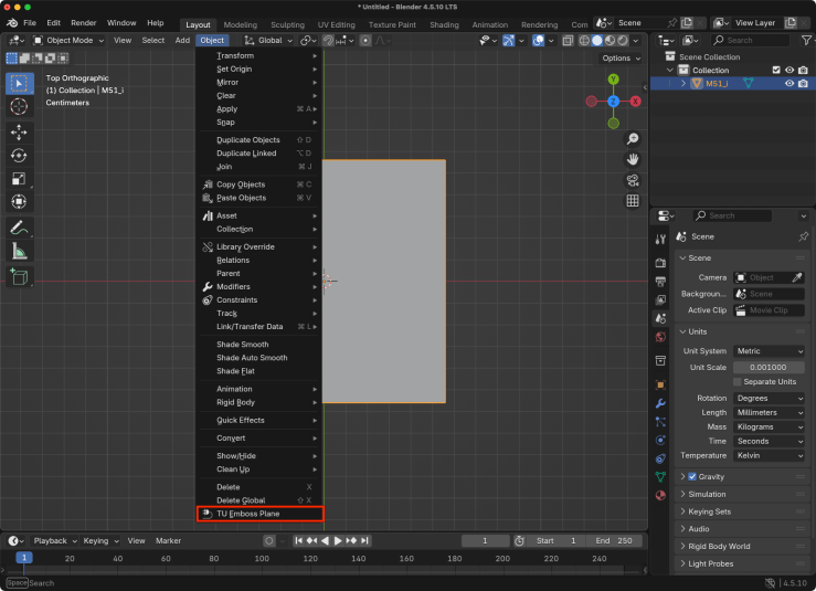
To use the emboss plane add-on select the plane and click Object > TU Emboss Plane in the menu. This menu option will be disabled if the add-on can’t be applied to the selected object.
Note: Unlike previous versions you don’t need to enter “edit mode.” The new version works in “object mode.”
3. Adjust the parameters
Once activated, you will see a model in the viewport using the default settings. These defaults can be adjusted by opening the “object” tab of the “properties” panel on the right-hand side of the user interface. Once selected, scroll down to the “TU Emboss Plane Properties” section. If you don’t see this section, make sure the main model is selected. If any of the other parts are selected (e.g. the name plate or back frame) these properties will not show up.
Note: the properties panel’s size can be adjusted by clicking and dragging its top or left edge. This can make reading the properties labels a bit easier.
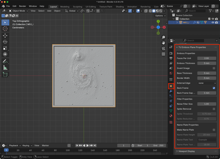
Once expanded you will see the settings are broken into three different sections:
Emboss Properties: These will change the base mesh the image is applied toFilter Properties: These are used for cleaning up noise and foreground starsName Plate Properties: These can be used to add a nameplate to the model
These parameters can be adjusted at any time even after saving and reloading the .blend file.
The individual parameters are the same as the previous version of the plugin, see section 3 of Tactile Universe add-on v5.0 for full descriptions of each one.
4. Export as STL
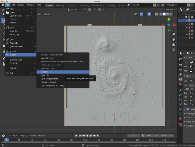
Go to File > Export > Stl to export the model
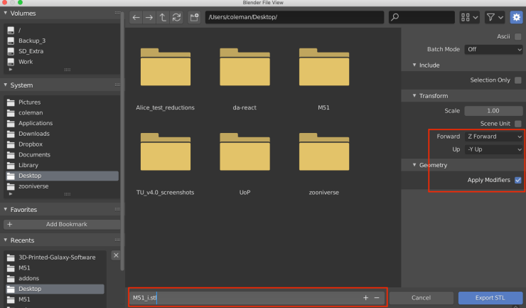
In the export dialog box make sure the Apply Modifiers box is checked and set Z Forward and -Y Up. This will ensure the model is facing the correct direction when imported in the 3D printer slicing program.
5. Slice and print
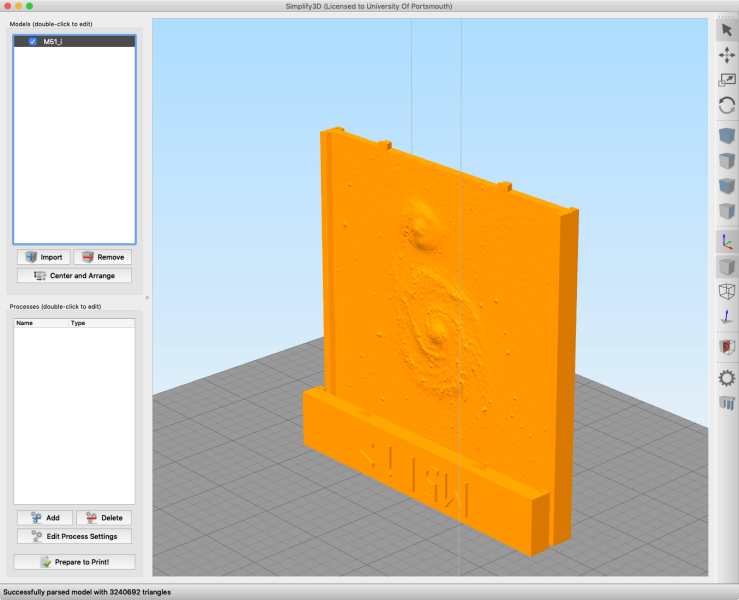
Import the STL file into your printer’s slicing program. It should be oriented on its edge (see image below) to ensure the best quality print. For more information about this process see our slicing and printing blog post.
Making a holder
This is a recap of 7. Making a Model Holder using the latest version of the TU add-on.
1. Make a holder for all your prints
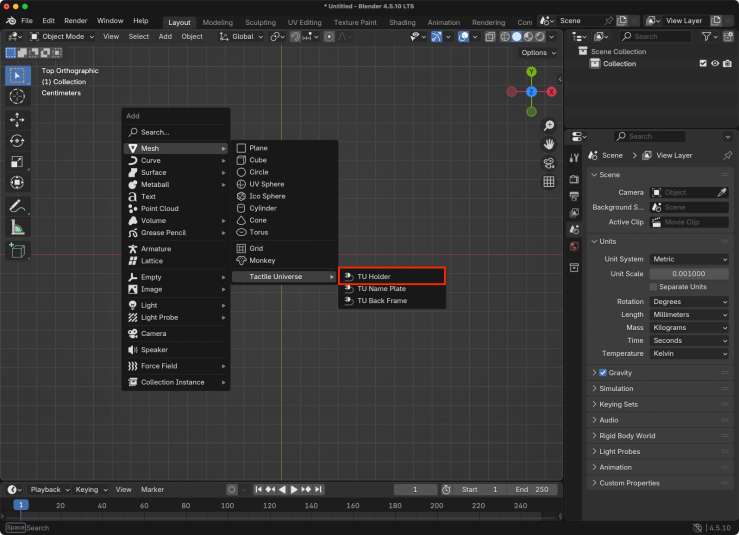
The next add-on we will look at is the TU Model Holder. This is used to create a holder for your 3D models. To make one start with an empty scene. Press shift + a to bring up the add menu and go to Add > Mesh > Tactile Universe > TU Holder.
2. Adjust the settings
Once activated, you will see a holder model in the viewport using the default settings. These defaults can be adjusted by opening the “object” tab of the “properties” panel on the right-hand side of the user interface. Once selected, scroll down to the “Holder Properties” section.
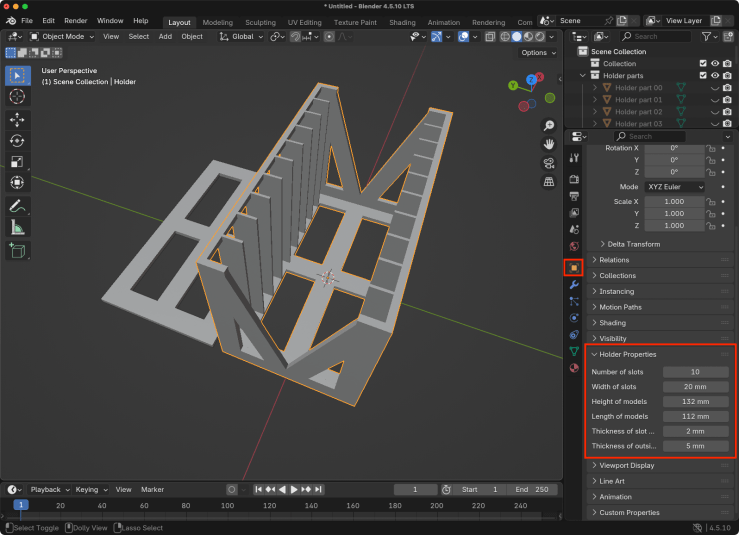
These settings will change the size of the holder in various ways.
Number of slots: This is the number of slots the holder will haveWidth of slots: This is how much space will be between each slatHeight of models: This is how high the models will be when placed in the holderLength of models: This sets how wide the holder will beThickness of slot walls: This sets the thickness of the slatsThickness of outside walls: This sets the thickness of all outside walls
This creates both a holder (right-hand side) and a lid (left-hand side). The holder will be selected by default. The holder and the lid are two separate objects that can be exported as STL files either separately or together. The Selection Only option in the STL export window can be used to only export the selected object. For the holder you will want to use the Y Forward and Z Up options during the export as well.
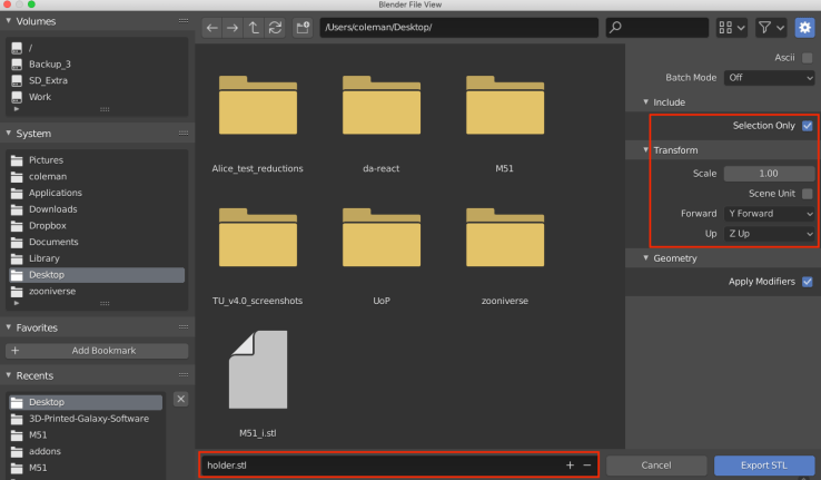
Unlike the previous versions of the add-on, the holder’s and the lid’s individual parts are joined into a single object to make it easier to select either one and import the resulting STL files into slicers.
3. Slice and print
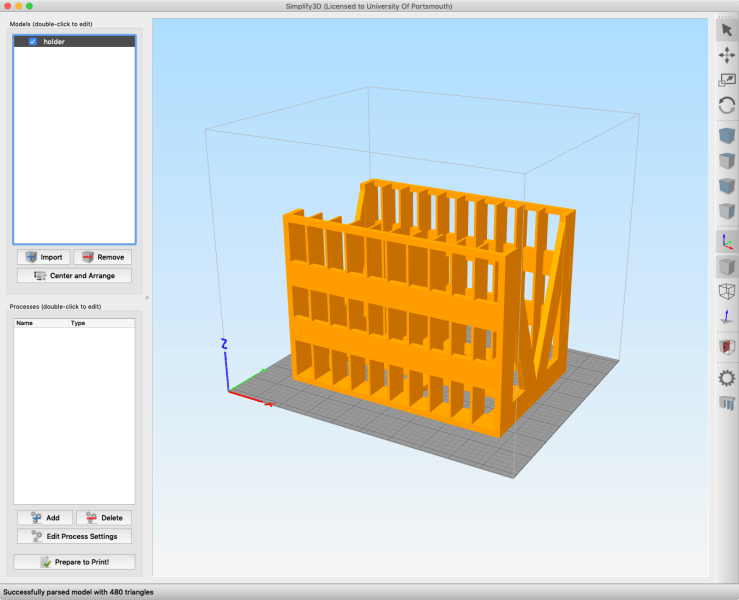
The holder STL can be imported into your printer’s slicer. See our slicing and printing blog post for more information on this process.
Individual name plate
Sometimes it can be useful to create just a name plate for a model.
1. Making a new name plate object
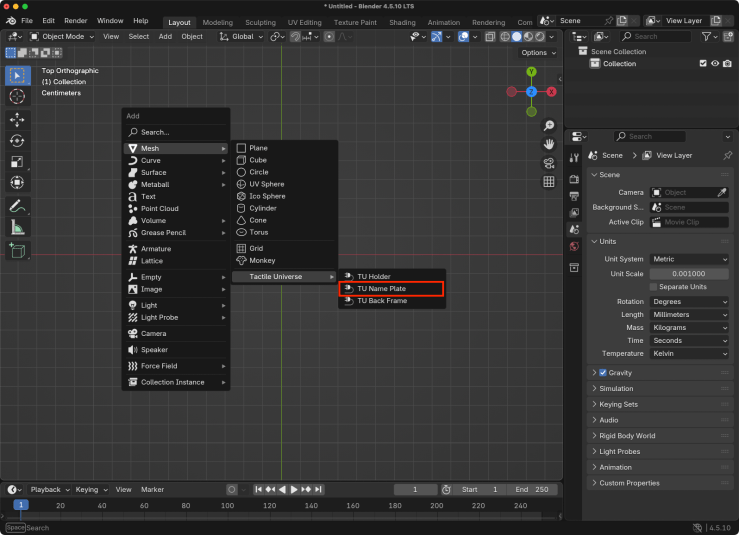
Press shift + a to bring up the add menu and go to Add > Mesh > Tactile Universe > TU Name Plate.
2. Adjust the settings
Once activated, you will see a name plate model in the viewport using the default settings. These defaults can be adjusted by opening the “object” tab of the “properties” panel on the right-hand side of the user interface. Once selected, scroll down to the “Name Plate Properties” section.
These settings will change the size and text of the name plate in various ways.
Size X: This is the size of the name plate in the X direction and adjusts the spacing of the notches if activated.Size Y: This is the size of the name plate in the Y directionSize Z: This is the size of the name plate in the Z directionText: The text to be displayed on the name plateText size: The size of the textNotches: If selected, notches will be added along the bottom edge of the name plate. The placement of these notices will line up with a model created with the sameSize X,Base height, andBorder widthvalues.Base height: Adjusts the height of the notchesBorder width: Adjust the depth of the notches
This creates a single name plate object that can be exported as an STL in the usual way.
Command line scripts
The command line scripts work in the same way as before. See the “How to make models on the command line” section of Tactile Universe add-on V5.0.

