
Since we first released our Tactile Universe add-ons six years ago Blender has undergone several significant updates. The latest major update (Blender 4.3.2 as of Jan 2025) has made some minor changes to the user interface and a few other changes under the hood. To keep up to date with these changes we have just released V5.0 of our add-on, and to go along with it this new tutorial for using it.
Much of the tutorial will be familiar if you have used our add-on before, but where things have changed we have included new screenshots and instructions.
Setting up Blender
This is a recap of 1. How to get started with Blender using the latest version of Blender.
1. Download
To make your own models you will need to download:
- The latest version of Blender (4.3.2 at the time of this post)
- The latest version of the Tactile Universe add-on (5.0.1 at the time of this post)
After unzipping the TU add-on you will see it has a TU_startup.blend file and a tactile_universe_plugin.zip file among others. These two files will be used below.
2. Adjust settings
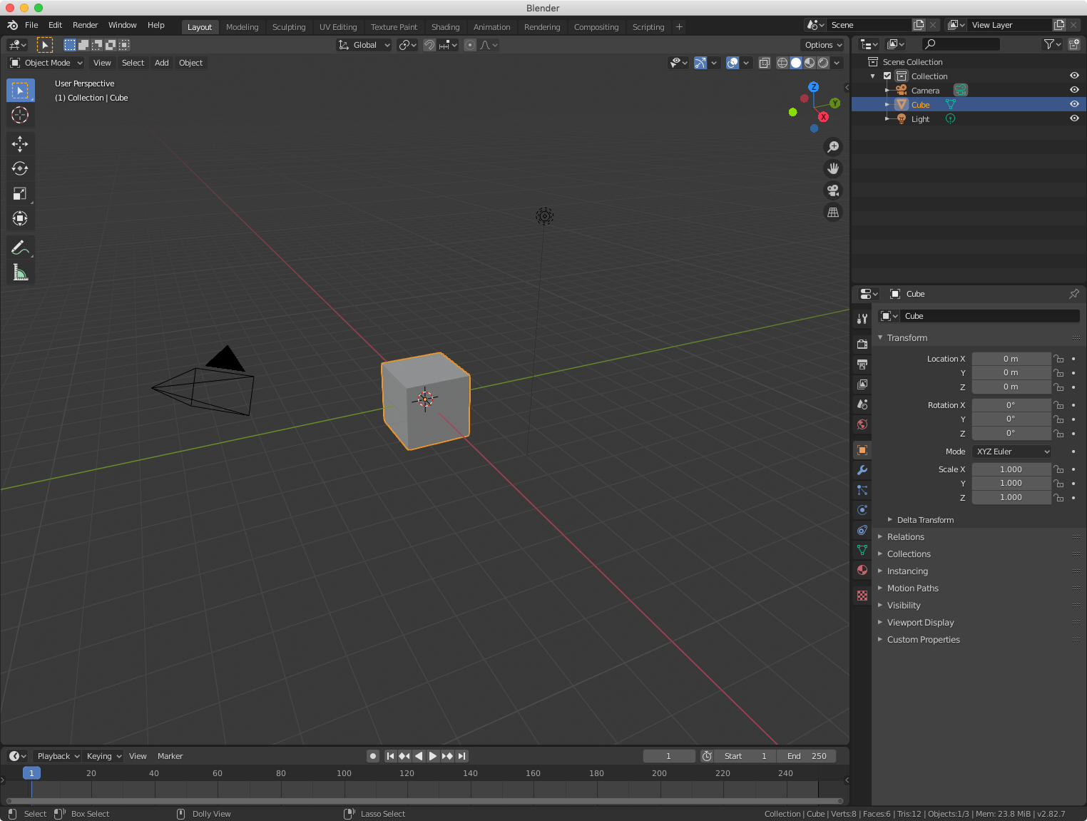
When you first open Blender you will see the following default cube, light, and camera. Let’s ignore those for the time being and instead adjust some of the settings.
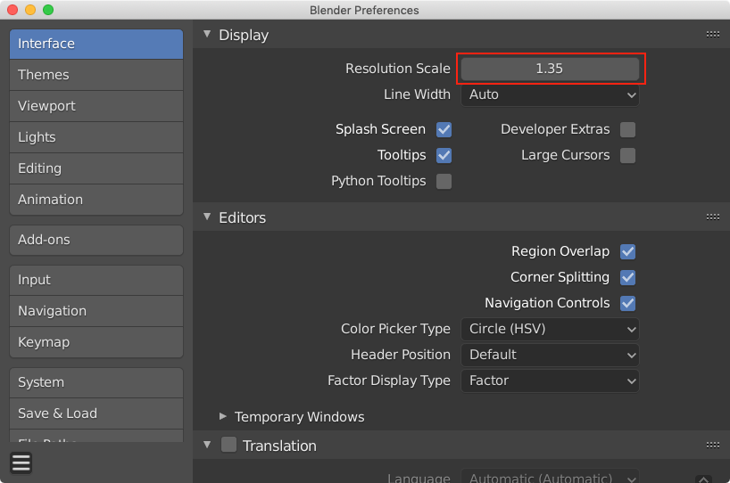
The settings are found in the Edit > Preferences menu.

Within the interface tab, the resolution scale option will make the default font size of the user interface larger. I find the default to be a bit on the small side.
If you are working on a laptop you can adjust some of the input settings to make things easier.

3. Install and activate Tactile Universe add-on
To install the TU add-on click the downward-pointing chevron in the upper right corner of the Add-ons tab. From the dropdown menu select the Install from Disk... button. In the file selection menu navigate to the tactile_universe_plugin.zip folder you downloaded earlier. This will install the emboss plane, TU name plate, TU back frame, and TU holder add-ons all in one go. TU back frame and TU name plate are helper functions that emboss plane uses, although they can be used on their own, it is not recommended.
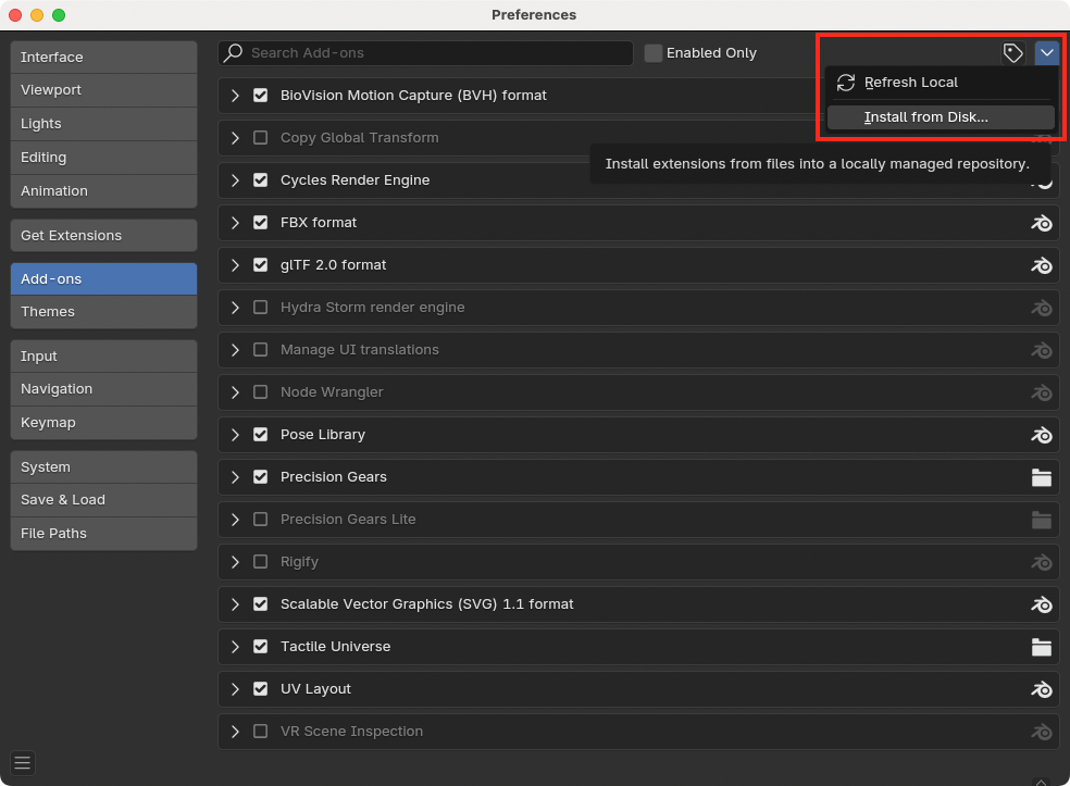
Once installed activate the TU add-on by checking the box next to its name (typically this will be checked by default).

4. Adjust some of the viewport settings
On my laptop, I found that Blender would sometimes freeze up when making a TU model. To fix this issue I needed to adjust the viewport quality settings to turn off Anti-Aliasing and Smooth Wires.

5. Set up a default scene
You can open up the TU_startup.blend file and skip directly to the “save startup” step, or you can set it up by hand by following this step.
Select all the objects in the scene by pressing a. Delete the objects by pressing x followed by clicking Delete in the popup prompt.

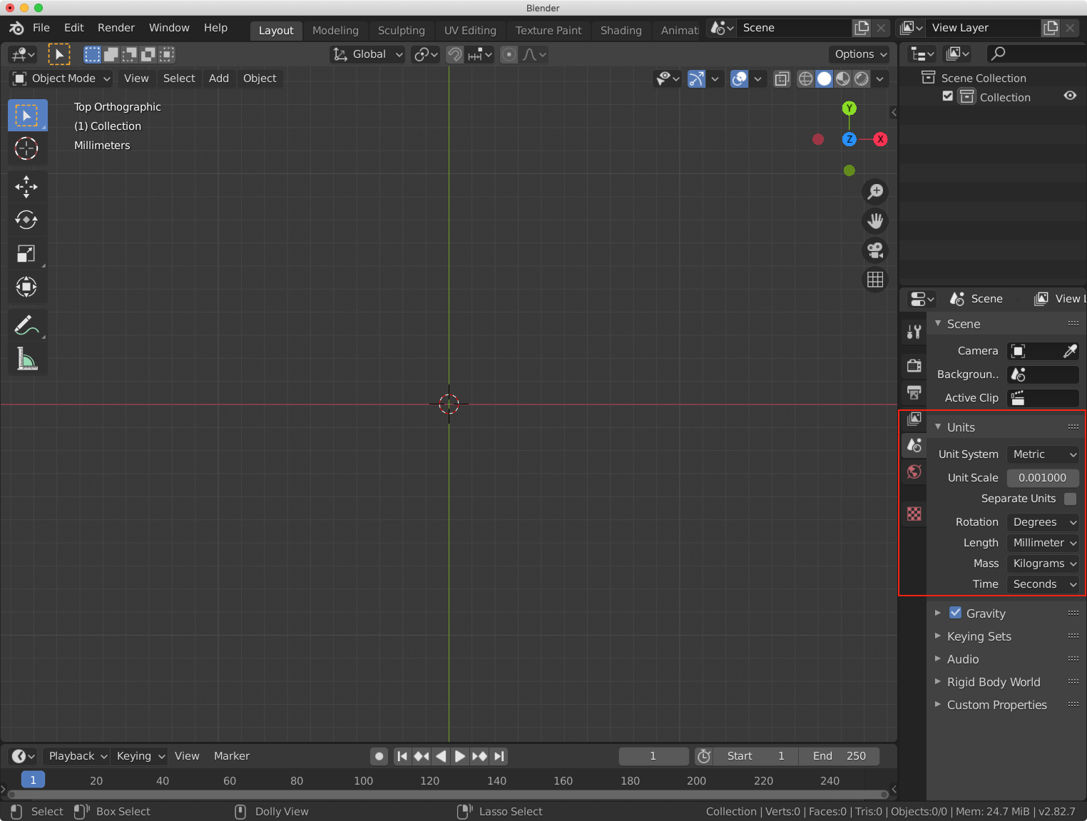
Next, we will set up Blender to use the correct units. 3D printers expect models to be made with a base unit of millimetres. In the lower right-hand panel go to the scene tab (the 5th one down) and go to the Units section. Set unit system to metric, unit scale to 0.001, and length to millimetres.
Save these settings as your startup file by going to File > Defaults > Save Startup File and clicking on the confirm button in the popup prompt.

Making your own models
This is a recap of 2. How to make your own models using the latest version of the TU add-on.
1. Import an image
To import an image press shift + a to bring up the add object menu, go to Image > Mesh Plane.

In the file selection box navigate to the image you want to make a model for. On the right-hand side of the window make sure to set the height of the model in millimetres. We typically use a height of 112 mm. The add-on includes an image of M51 you can use for testing.

2. Use the Emboss Plane add-on
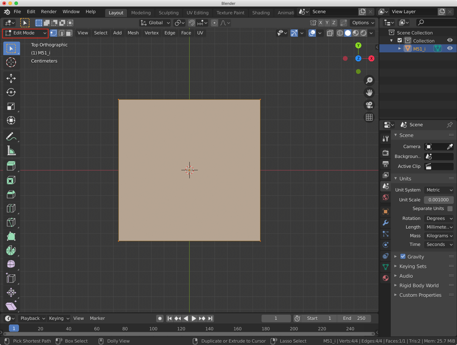
To use the emboss plane add-on the plane you just added needs to be in edit mode. This can be done by pressing tab or using the mode menu highlighted in the image below.
Note: the mode menu might appear along the bottom of the viewport rather than the top, this is dependent on Blender’s window size.
Once in edit mode click Mesh > TU Emboss Plane to activate the add-on.

3. Adjust the parameters
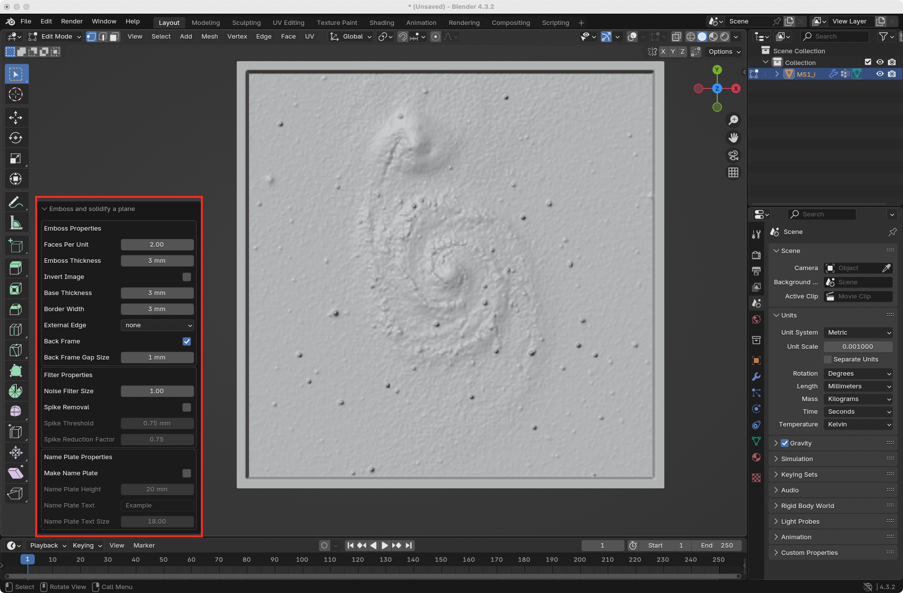
Once activated you will see a galaxy model in the viewport using the default settings. These defaults can be adjusted by expanding the add-on’s parameter box in the lower left of the viewport.

Once expanded you will see the settings are broken into three different sections:
Emboss Properties: These will change the base mesh the image is applied toFilter Properties: These are used for cleaning up noise and foreground starsName Plate Properties: These can be used to add a nameplate to the model
Let’s go over what each parameter does.

Faces per unit
This changes the density of the base mesh. The higher this number is the more detailed the resulting model will be. It will default to 2 faces per millimetre, a reasonable value for hand-sized models. For illustration let’s change the value to 1 face per millimeter.
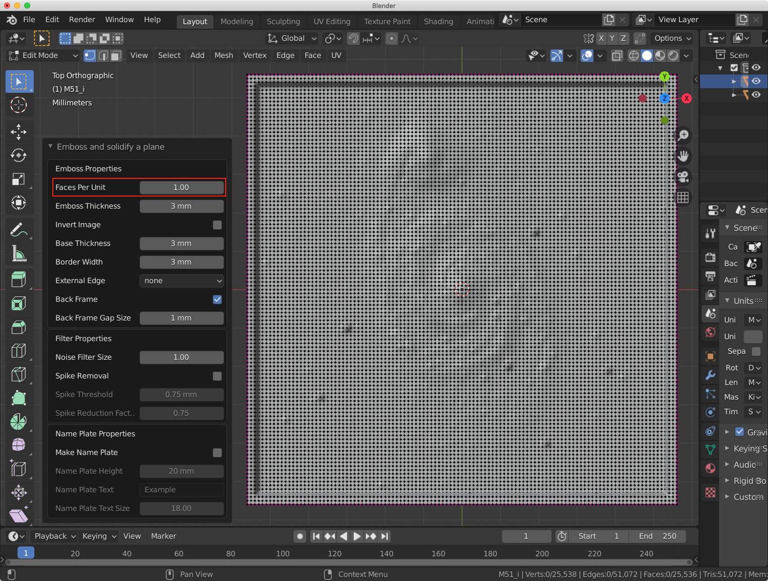
After this change, you can see the galaxy model has far fewer faces (represented by the black dots across the model).
Emboss Thickness
This sets how high the brightest part of the image (pure white) will be in relation to the darkest part (pure black). This is indicated by the arrow in the image below.
For larger models, this value should be increased and the faces per unit decreased.

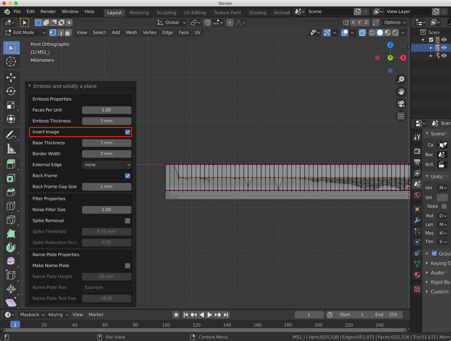
Invert Image
This will invert the direction of the height map. Black will be the highest point and white the lowest.
Base Thickness
This is how far below the image the model extends. This distance is indicated by the arrow in the image below.

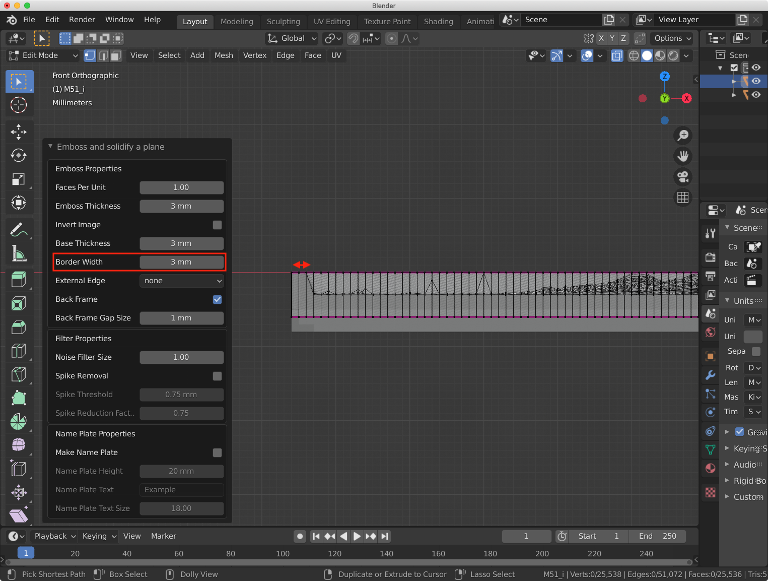
Border Width
How thick the border around the outside is. This is shown by the arrow in the image below.
External Edge
This dropdown menu allows you to pick an edge to print as a separate object. The external edge is automatically placed in the correct spot for printing (models are printed on their edge, see the image near the end of this post for more information). Notches and wedges are also added to help align the edge when attaching it to the model.

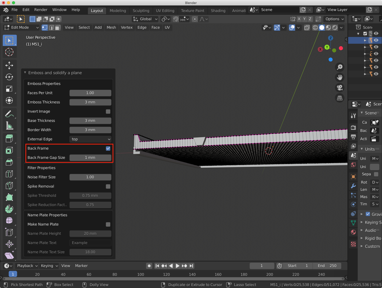
Back Frame and Back Frame Gap Size
These settings add a frame on the back side of the model that can be used to hold an image printed on paper. The gap size is how much space is left between the back of the model and the frame (i.e. the thickness of the paper being inserted).
Nose Filter Size
This setting can be used to smooth out any noise in the image. A value of 1 indicates no filtering is done, and increasing the value increases the smoothness. To show the effects of this easier we will put the faces per unit value back up to 2 and turn off the black dots across the image (highlighted button in the top right of the viewport).

Increasing the filter size to 5 we can see how much smoother the background of the image is.

Spike Removal, Spike Threshold, and Spike Reduction Factor
An image with lots of foreground stars can turn out quite spiky. These spikes can end up being quite sharp once printed, so these options will allow them to be reduced in size.

By turning on spike removal any single vertex spikes are identified and lowered in size. All spikes higher than the threshold value are reduced in height by the reduction factor value. When the vertex dots are visible any identified spikes will be highlighted.

Name Plate, Name Plate Height, Name Plate Text, and Name Plate Text Size
A nameplate can be added to a model using these settings. The height, text, and font size can be set with these parameters. If an external edge is being used this will replace it, otherwise it is placed along the top of the model.
After creating the model the font used for the text can be changed on the text object. We do not recommend using a braille font, as getting it to be the correct spacing can be quite challenging. Instead, we recommend making a blank nameplate (i.e. set the text to be blank) and attaching braille stickers to the model after printing.

Side note
If you click away or deselect the model in the viewport the settings panel will be automatically closed. It can be brought back by pressing the F9 key as long as no other object has been edited in the scene.
F9 key4. Export as STL
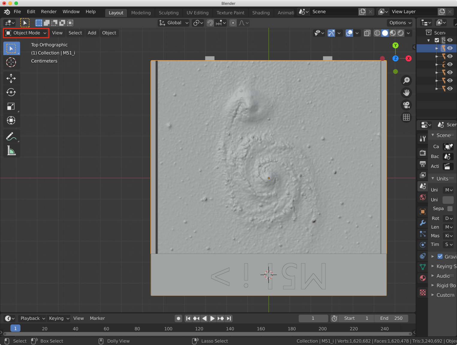
Once done, enter back into object mode with the tab key or use the mode menu.
Go to File > Export > Stl to export the model.

In the export dialog box make sure the Apply Modifiers box is checked and set Z Forward and -Y Up. This will ensure the model is facing the correct direction when imported in the 3D printer slicing program.

5. Slice and print
Import the STL file into your printer’s slicing program. It should be oriented on its edge (see image below) to ensure the best quality print. For more information about this process see our slicing and printing blog post.

Making a holder
This is a recap of 7. Making a Model Holder using the latest version of the TU add-on.
1. Make a holder for all your prints
The next add-on we will look at is the TU Model Holder. This is used to create a holder these 3D models can be placed in. To make one start with an empty scene. Press shift + a to bring up the add menu and go to Add > Mesh > TU Model Holder.

2. Adjust the settings
These settings will change the size of the holder in various ways.
Number of slots: This is the number of slots the holder will haveWidth of slots: This is how much space will be between each slatHeight of models: This is how high the models will be when placed in the holderLength of models: This sets how wide the holder will beThickness of slot walls: This sets the thickness of the slatsThickness of outside walls: This sets the thickness of all outside walls
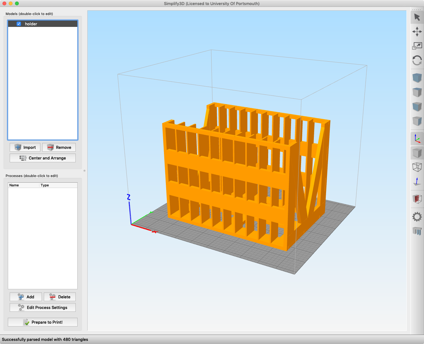
This creates both a holder (right-hand side) and a lid (left-hand side). All parts of the holder will be selected when the add-on is done running.

3. Export the holder
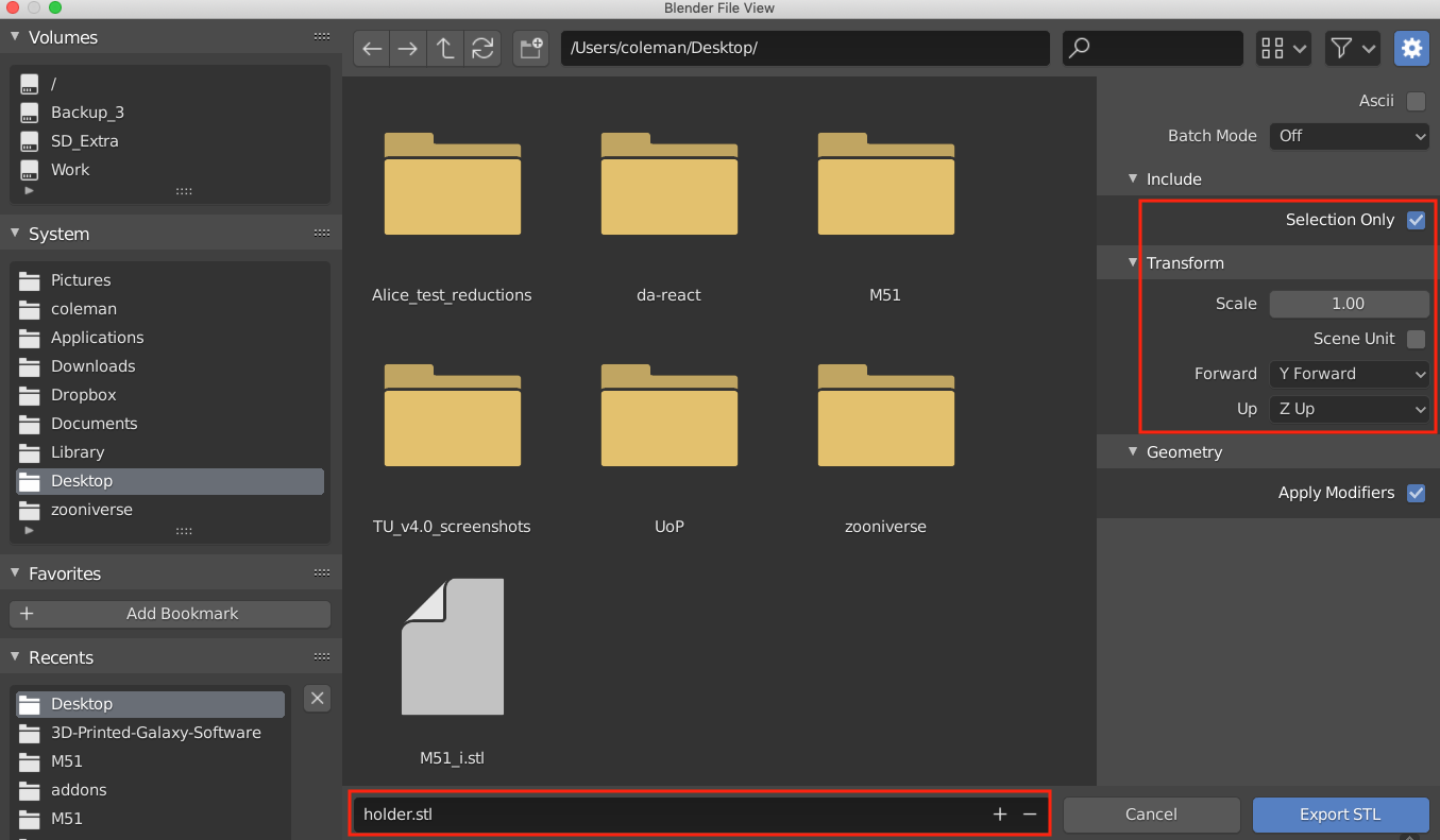
The holder and lid together are too big to print in one go, so we will export them as separate STL files. With the holder selected go to File > Export > Stl.

In the export window make sure Selection Only is selected, Y Forward is set, and Z Up is set.
4. Invert selection and export the lid
Next, we will select the lid by going to Select > Invert and export it just like we did the holder.


5. Slice and print
The holder STL can be imported into your printer’s slicer. See our slicing and printing blog post for more information on this process.
How to make models on the command line
This is an update of 3. How to make models on the command line with the latest version of Blender. This is mostly the same as before, so only sections that have changed will be covered here.
Setting up Blender to run from the command line
To get started we need to set up blender to be run from the command line. This is outlined nicely in the official documentation. For me, this involved setting up an alias to the blender executable on my Mac (bash shell):
echo "alias blender=/Applications/Blender.app/Contents/MacOS/blender" >> ~/.bash_profile
On the Windows (cmd.exe) this is:
DOSKEY blender="C:Program FilesBlender FoundationBlenderblender.exe"
Making configuration files
The command line script requires a configuration json file to be passed in, this file contains all the information needed to create a model. This file is structured as follows:
{
  "input_file_path": "M51_i.png",
  "plane_height": 112,
  "emboss_plane_keywords": {
    "Fpu": 2,
    "Emboss_height": 3,
    "Invert_image": false,
    "Base_height": 3,
    "Border_width": 3,
    "External_edge": "TOP",
    "Back_frame": true,
    "Gap_size": 1,
    "Noise_filter": 1,
    "Spike_removal": true,
    "Spike_threshold": 0.75,
    "Spike_reduction_factor": 0.75,
    "Name_plate": true,
    "Name_plate_Y": 20,
    "Name_plate_text": "M51 i >",
    "Name_plate_text_size": 18
  },
  "stl_keywords": {
    "forward_axis": "Z",
    "up_axis": "NEGATIVE_Y"
  },
  "output_path": "/path/to/output/folder",
  "output_name": "M51_i"
}
See the previous sections of this post for an overview of what these settings do. Any keywords not specified will use the defaults shown in the previous sections of this post.
Note
The format of the “stl_keywords” section has changed since the previous versions of Blender, if you have previously made configuration files you would like to reuse they will need to be updated.
How to make holders on the command line
This is exactly the same as before, see the end of 7. Making a Model Holder for instructions.
